FPLC EQUIPMENT
There are variations in the FPLC equipment depending of the different manufacturers, such as Pharmacia and AKTA.
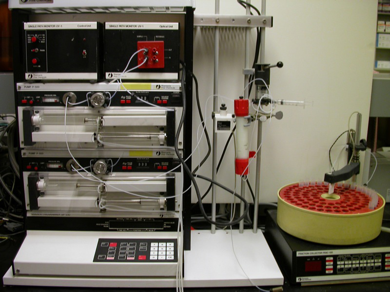
Pharmacia FPLC system
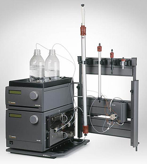
AKTA FPLC system
However, an elementary FPLC system is basically composed by:
1. A Program controller
2. Two pumps
3. A Mixer
4. An injection loop
5. An Injection valve
6. A Column
7. An Ultraviolet monitor
8. A Fraction collector
9. Monitor or recorder
Although it is possible to operate the system manually, the components are normally linked to a personal computer or, in older units, a microcontroller.
1. Program controller
This is a control unit essential in chromatography systems. This unit enables users to control the process, modify separation parameters, control fraction collectors, evaluate data and also print information from the chromatogram.
This is a control unit essential in chromatography systems. This unit enables users to control the process, modify separation parameters, control fraction collectors, evaluate data and also print information from the chromatogram.
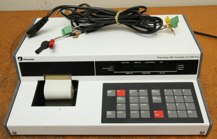
(LCC 500 Plus)
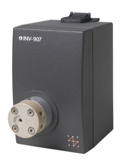
2. Pumps
These pumps are used in chromatography and other processes where keep a constant flow rate is essential. These units can work accurately on low and high flow rates in their whole pressure range. GE/Pharmacia systems utilize two two-cylinder piston pumps, one for each buffer, combining the output of both in a mixing chamber. Waters systems use a single peristaltic pump which draws both buffers from separate reservoirs through a proportioning valve and mixing chamber. In either case the system allows the fraction of each buffer entering the column to be continuously varied. The flow rate can go from a few millilitres per minute in bench-top systems to litres per minute for industrial scale purifications. The wide flow range makes it suitable both for analytical and preparative chromatography.
These pumps are used in chromatography and other processes where keep a constant flow rate is essential. These units can work accurately on low and high flow rates in their whole pressure range. GE/Pharmacia systems utilize two two-cylinder piston pumps, one for each buffer, combining the output of both in a mixing chamber. Waters systems use a single peristaltic pump which draws both buffers from separate reservoirs through a proportioning valve and mixing chamber. In either case the system allows the fraction of each buffer entering the column to be continuously varied. The flow rate can go from a few millilitres per minute in bench-top systems to litres per minute for industrial scale purifications. The wide flow range makes it suitable both for analytical and preparative chromatography.
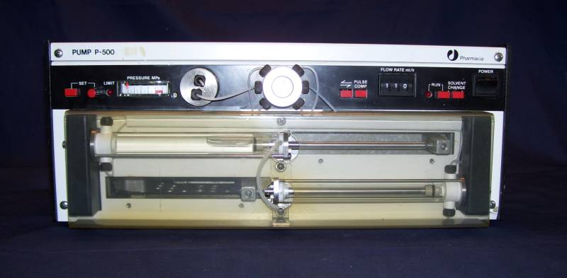
Pump P-500
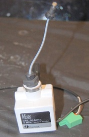
3. Mixer
This component allows users to mix the buffers and run a gradient from low concentration to high concentration of either buffer. All effluents can be mixed with a high degree of precision.
This component allows users to mix the buffers and run a gradient from low concentration to high concentration of either buffer. All effluents can be mixed with a high degree of precision.
4. Injection loop
A segment of tubing of known volume which is filled with the sample solution before it is injected into the column. Loop volume can range from a few microliters to 50ml or more.
A segment of tubing of known volume which is filled with the sample solution before it is injected into the column. Loop volume can range from a few microliters to 50ml or more.
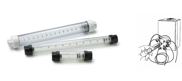
5. Injection valve
An injection valve is a motorized valve which links the mixer and sample loop to the column. Typically the valve has three positions for loading the sample loop, for injecting the sample from the loop into the column, and for connecting the pumps directly to the waste line to wash them or change buffer solutions. The injection valve has a sample loading port through which the sample can be loaded into the injection loop, usually from a hypodermic syringe using a Luer-lock connection. This valve is used to inject samples into the column. It is important due to it allows the loading of the sample without disturbing the column equilibration.
An injection valve is a motorized valve which links the mixer and sample loop to the column. Typically the valve has three positions for loading the sample loop, for injecting the sample from the loop into the column, and for connecting the pumps directly to the waste line to wash them or change buffer solutions. The injection valve has a sample loading port through which the sample can be loaded into the injection loop, usually from a hypodermic syringe using a Luer-lock connection. This valve is used to inject samples into the column. It is important due to it allows the loading of the sample without disturbing the column equilibration.
Samples can be injected in a range of 1 to 150 ml using syringes of 10ml, 50ml and 150ml.
6. Column
Commonly, a chromatographic column is a tube made by glass which has varied diameter, from 5 mm to 50 mm and height from 5 cm to 1 meter. The column is semi-sealed in the bottom with a kind of filter that allows the precipitation of loaded samples. Columns are packed with beads of resin, known as stationary phase, and filled with buffer solution. It is normally mounted vertically with the buffer flowing downward from top to bottom. A glass frit at the bottom of the column retains the resin beads in the column while allowing the buffer and dissolved proteins to exit.
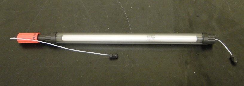
7. Ultraviolet monitor
This unit measures the UV absorption, pH and conductivity of the sample of interest (cells flow rate).
This unit measures the UV absorption, pH and conductivity of the sample of interest (cells flow rate).
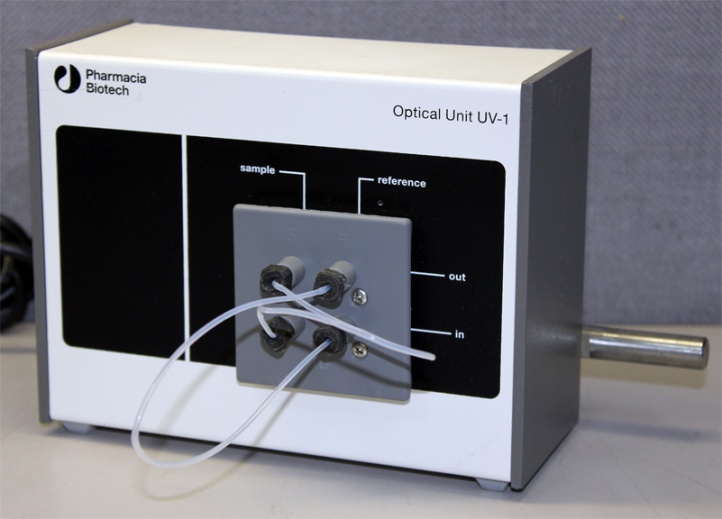
Uv1 monitor
8. Fraction collector
The fraction collector is typically a rotating rack that can be filled with test tubes or similar containers. The fraction collector accumulates fractions based either on time, volume or drop counting, controlled by programs specified by the users.
The fraction collector is typically a rotating rack that can be filled with test tubes or similar containers. The fraction collector accumulates fractions based either on time, volume or drop counting, controlled by programs specified by the users.
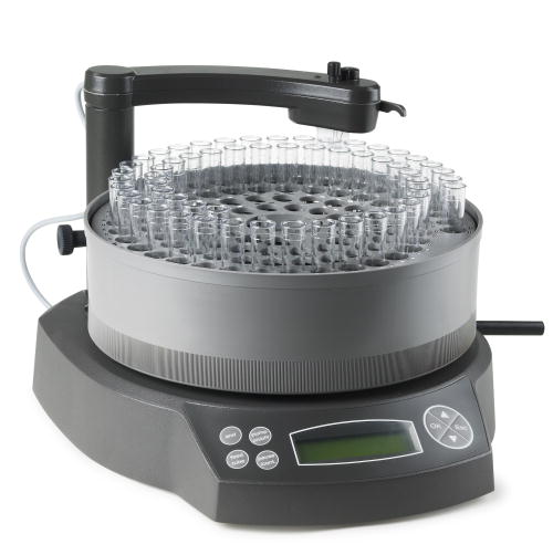
Frac-100 collector
9. Monitor or Recorder
The flow cells are connected to a display and/or recorder. On older systems this was a simple chart recorder, on modern systems a computer with hardware interface and display is used. This permits the experimenter to identify when peaks in protein concentration occur, indicating that specific components of the mixture are being eluted.
Many systems include various optional components. A filter may be added between the mixer and column to minimize clogging. In large FPLC columns the sample may be loaded into the column directly using a small peristaltic pump rather than an injection loop. When the buffer contains dissolved gas, bubbles may form as pressure drops where the buffer exits the column; these bubbles create artifacts if they pass through the flow cells. This may be prevented by degassing the buffers, or by adding a flow restrictor downstream of the flow cells to maintain a pressure of 1-5 bar in the effluent line.
